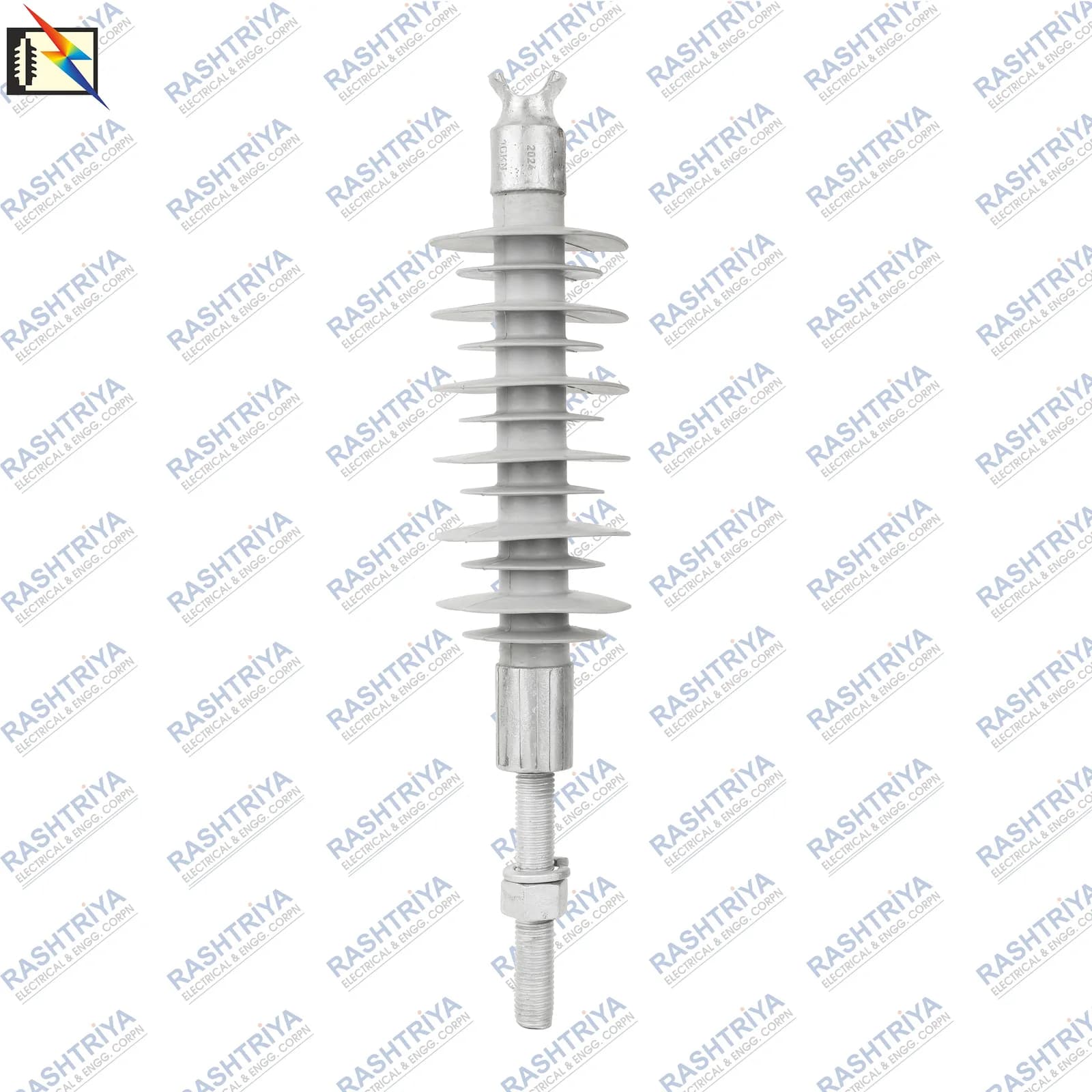
Overhead conductors must be mechanically supported while remaining electrically isolated from the pole, cross-arm and other grounded structures. A Polymer Pin Insulator combines these two duties:
Electrical insulation + mechanical conductor support
Depending on regional and commercial terminology, it may also be described as a Composite Pin Insulator, Composite Polymer Pin Insulator, Silicone Rubber Pin Insulator, Polymeric Pin Insulator, Distribution Pin Insulator, FRP Core Pin Insulator or Pin-Type Polymer Insulator. These names can overlap, but the actual construction, mounting arrangement and approved specification remain more important than the label.
Voltage alone is not enough to select the right product. A useful engineering sequence is:
Polymer pin insulator selection flow
- Application
- Voltage
- Mechanical strength
- Creepage
- Pin / mounting compatibility
- Conductor arrangement
- Electrical insulation
- Applicable specification
This guide explains the technical terms behind that sequence. For product-level specifications, price and availability, see the Polymer Pin Insulator range. For an overview of the wider family, begin with the Polymer Insulators: Disc, Post & Pin Guide.
What Is a Polymer Pin Insulator?
A Polymer Pin Insulator is a rigid insulating support used to carry an energized overhead conductor while maintaining electrical separation from the cross-arm, pole hardware or other grounded structure.
In a typical pin-mounted arrangement, the lower fitting interfaces with a pin or support fixed to the cross-arm. The conductor is supported at the upper end by a groove, tie, clamp or another approved conductor arrangement. The exact hardware varies with the product and line design.
The word pin describes an important mounting concept, but it does not by itself define every mechanical dimension, test requirement or product standard.
Some composite products sold commercially as pin insulators may resemble rigid line-post designs. Classification should therefore follow the actual construction + mounting arrangement + mechanical definition + applicable specification, not appearance or catalogue wording alone.
Construction of a Polymer Pin Insulator
A typical solid-core polymer pin insulator combines a load-bearing internal core, an external polymer housing, weather sheds and metallic mounting hardware. Performance depends on the complete assembly and its interfaces—not on any one material in isolation.
FRP / GRP Core
The central structural element is commonly a fibre-reinforced resin core, described as FRP (fibre-reinforced polymer) or GRP (glass-reinforced plastic).
Glass fibres embedded in a resin matrix provide the principal mechanical load path while also remaining electrically insulating. The core must transfer conductor loads to the mounting fitting, but its diameter alone does not establish the rating. Fibre system, resin, interfaces, end connection and tested assembly all matter.
Silicone Rubber Housing
The FRP core is normally enclosed by a polymeric housing. Silicone rubber is widely used because it provides external electrical insulation, protects the internal structure and can offer hydrophobic surface behaviour.
Hydrophobicity can help water form droplets rather than a continuous surface film. It should not be described as permanent under every condition: UV exposure, contamination, corona, dry-band arcing, material formulation and ageing can alter surface behaviour over time.
Weather Sheds
The projecting profiles around the body are the weather sheds. They extend and shape the surface insulation path and influence rain and pollution performance.
Shed count alone is not a performance rating. Shed diameter, spacing, overhang, profile, housing diameter, orientation and the complete electric-field environment are also relevant.
Metallic Pin / Mounting Fittings
Metallic fittings connect the insulating body to the supporting structure and, where applicable, to conductor hardware. Depending on an approved design, fitting materials may include SG/ductile iron, malleable cast iron, forged steel or another engineered material.
This is not a list of materials present in every product. The approved drawing and GTP should confirm material, coating, thread, dimensions, engagement length, washer/nut arrangement and corrosion protection.
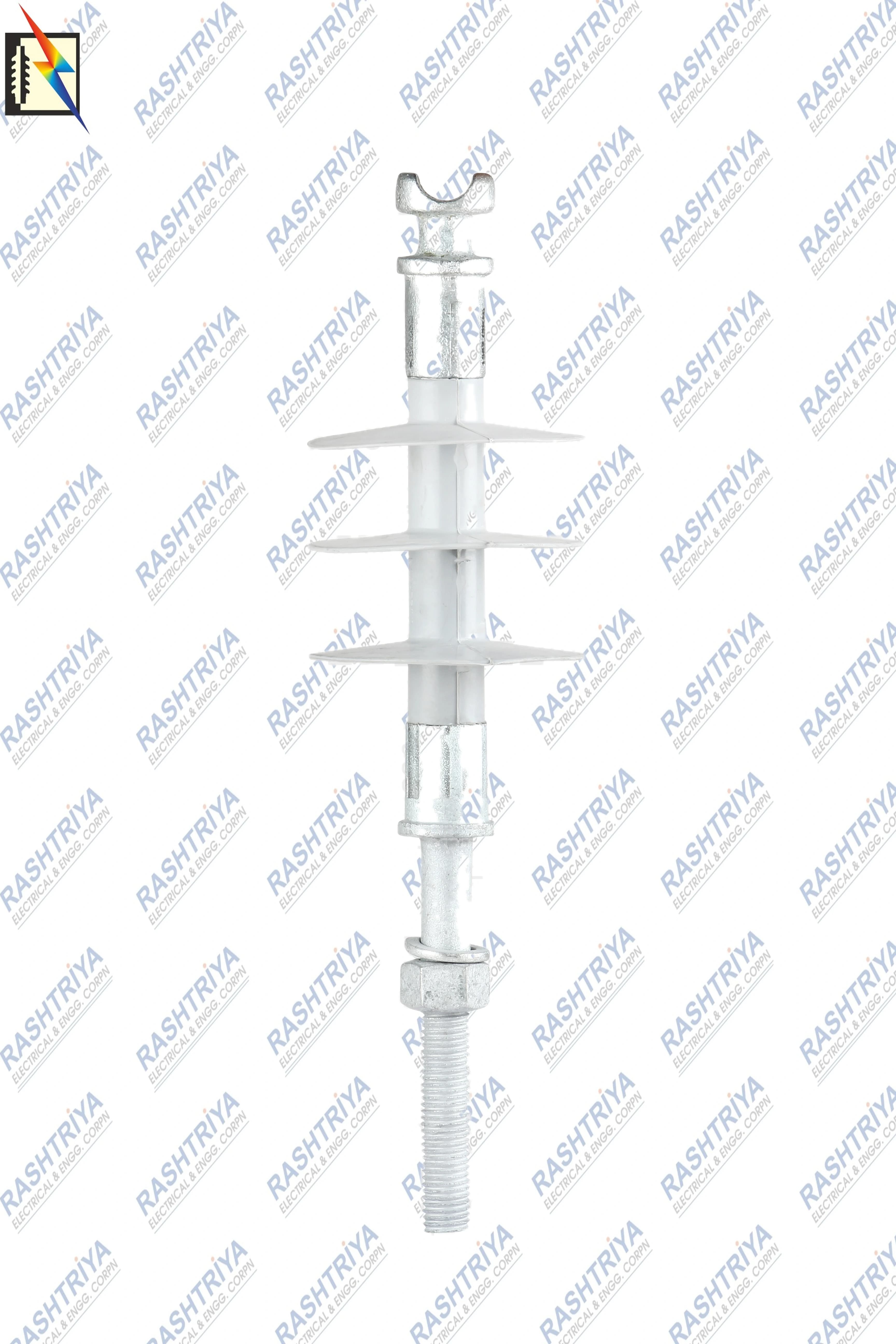
- Conductor SupportTop fitting and conductor-support interface
- Silicone Rubber ShedsProfiled external insulating surface
- FRP Core — InternalStructural insulating core beneath the housing
- Pin / Mounting FittingMechanical interface to the supporting structure
The labelled core in this visual is internal; it is not normally visible through the finished silicone-rubber housing.
How Does a Polymer Pin Insulator Work?
The mechanical load path can be simplified as:
Conductor → insulator → pin or mounting fitting → cross-arm / structure
At the same time, the insulating body separates the energized conductor from grounded hardware. These functions occur together, so electrical suitability cannot compensate for an incompatible mounting interface or inadequate mechanical duty.
Surface path
Creepage Distance
The distance measured along the insulating surface between conductive parts. It is especially important under polluted and wet conditions.
Air path
Dry Arcing Distance
An external air-path characteristic between conductive parts. It is not the same measurement as creepage distance.
Physical size
Overall Height
A dimensional characteristic that can affect clearances and installation, but does not replace electrical ratings.
Mechanical interface
Pin Dimension
The geometry that must match the pin, cross-arm and fastening arrangement defined by the approved drawing.
Polymer Pin Insulator vs Polymer Line Post Insulator
Commercial terminology can overlap, particularly where a rigid composite body is mounted on a distribution structure. A Pin Insulator and a Composite Line Post Insulator should not automatically be treated as identical.
| Comparison | Polymer Pin Insulator | Polymer Line Post Insulator |
|---|---|---|
| Mounting concept | Commonly interfaces with a pin or pin-type support | Commonly uses a defined base fitting, gain base, line fitting or braced arrangement |
| Main function | Rigid conductor support and electrical separation | Rigid conductor support and electrical separation |
| Mechanical definition | Must be taken from the product GTP/drawing | Commonly defined using line-post mechanical terminology under the applicable specification |
| Typical installation | Distribution or sub-transmission pole/cross-arm arrangement | Vertical, horizontal or braced overhead-line arrangement |
| Conductor hardware | Groove, tie, clamp or approved top arrangement | Tie top, clamp top, blade or other approved line-end fitting |
| Primary selection inputs | Voltage, load, creepage, pin geometry, conductor support and withstand values | Voltage, cantilever duty, creepage, orientation, end fittings and withstand values |
| Product classification | Confirm from actual construction and governing project specification | IEC 61952-1 may apply when the actual product is a composite line-post design within its scope |
The safe classification test is:
Actual construction + mounting arrangement + mechanical definition + applicable specification
If a supplier drawing calls a product a pin insulator while a project specification treats the design as a line post, the discrepancy should be resolved before approval—not after delivery.
Polymer Pin Insulator Voltage Ratings
Polymer pin insulators may be requested in catalogue or project classes such as 11kV, 12/15kV, 22kV, 33kV and 44kV. Higher-voltage search terms, including 66kV, should only be treated as an available pin-insulator product when an actual approved design and current product record support that claim.
Individual product data remains authoritative. A voltage label on a product name does not fully describe its insulation system.
Network label
Rated Voltage
The nominal or assigned voltage class used to describe the application. It is not itself a test withstand value.
Equipment basis
Highest System Voltage
The maximum system-voltage basis associated with the equipment class when specified. It can differ from nominal voltage.
AC test
Power-Frequency Withstand
A specified dry or wet test-survival level under defined test conditions.
Impulse test
Lightning Impulse Withstand
A specified ability to withstand a standardized impulse test. It is not obtained simply by reading the nominal voltage.
Therefore:
Rated voltage ≠ highest system voltage ≠ power-frequency withstand ≠ lightning impulse withstand
Rated Voltage and Highest System Voltage
Verified catalogue examples illustrate the distinction:
- a recorded 22kV product example lists 25kV as its highest system voltage;
- recorded 33kV product examples list 36kV as their highest system voltage.
These are catalogue examples, not a rule for deriving one value from the other. If an approved product record does not state the highest system voltage, obtain it from the GTP or project documentation rather than estimating it.
What Does 5kN or 10kN Mean?
kN means kilonewton, a unit of mechanical force. Values such as 5kN and 10kN can identify mechanical classes in polymer pin-insulator product data.
They do not mean:
- current in amperes;
- short-circuit breaking current;
- system voltage;
- electrical withstand voltage.
Possible mechanical load sources include conductor weight, wind, conductor tension, vibration, line geometry and the mounting arrangement. Dynamic effects, load direction, lever arm and safety factors can also matter.
Catalogue example
5kN
A recorded mechanical class for certain product configurations. Confirm the exact load definition, direction and test basis in the product GTP.
Catalogue example
10kN
A higher recorded class for certain configurations, but not an automatic substitute for a line-design calculation or working-load limit.
Possible load sources
Installation Loads
Conductor weight, wind, conductor tension, vibration, line geometry and mounting arrangement must be considered together.
Pin Dimensions & Mounting Compatibility
Commercial searches and product names can contain figures such as 14mm, 16mm or 24mm. These numbers should be treated as identification clues—not as a complete mounting specification.
A single number may refer to a particular pin feature in one product family, while another drawing may define the interface differently. Never assume it describes the complete thread, shank or mounting system.
Replacement selection can require:
- the exact measured pin feature and its measurement location;
- thread diameter, pitch, form and usable engagement;
- mounting length and shoulder geometry;
- cross-arm hole or support interface;
- washer, nut and locking arrangement;
- overall geometry and orientation;
- an approved dimensional drawing.
For a replacement requirement, photograph the installation for context, but also measure the interface and provide the existing drawing or GTP. Selection from a photograph alone is unreliable.
What Is Creepage Distance?
Creepage distance is the distance measured along the insulating surface between conductive parts.
It is relevant because outdoor contamination can collect on the housing. Dust, moisture, industrial pollution, salt spray and coastal contamination can combine to form a more conductive wet surface layer. Leakage current and localized drying can then increase surface electrical stress.
Creepage is therefore a surface-path concept. It is not the straight-line height of the insulator and not the air path between fittings.
The drawing is conceptual; the correct creepage value must come from an approved product drawing or verified GTP.
Total Creepage vs mm/kV
Creepage can be presented in different ways:
- total creepage distance, such as a recorded 1100mm product configuration; or
- a specific-creepage notation, sometimes shown in catalogue/search wording as a value in mm/kV.
These are not automatically equivalent. A total length is a physical surface-path measurement. A value in mm/kV is a normalized relationship whose voltage basis and methodology must be known.
A product name containing 31mm/kV does not establish that 31mm/kV is required for every 33kV installation. Likewise, a 1100mm product example does not make 1100mm the universal creepage for every product at that nominal voltage.
Specific Creepage Distance and USCD
USCD means Unified Specific Creepage Distance. Conceptually, it relates total creepage distance to the relevant RMS operating voltage across the insulator:
The voltage basis matters. Phase-to-phase system voltage, voltage across the insulator and the definitions in the governing pollution-selection method must not be interchanged casually.
Values sometimes encountered in tenders or searches—such as 25mm/kV, 31mm/kV or 35mm/kV—are not universal rules. The approved utility specification, project pollution assessment and applicable IEC methodology should govern.
Simplified Creepage Relationship
For dimensional understanding only:
This relationship is not a complete product-selection calculation. Final external-insulation selection may also require consideration of:
- site pollution severity;
- shed profile and spacing;
- insulating material;
- altitude and atmospheric conditions;
- orientation;
- diameter correction where applicable;
- actual operating and wetting conditions;
- utility or project experience.
IEC TS 60815-1 and IEC TS 60815-3 provide pollution-selection guidance rather than a single creepage number that applies everywhere.
Creepage Distance vs Dry Arcing Distance
These terms describe different paths and should not be substituted for one another.
Along the surface
Creepage Distance
Measured along the external insulating surface between conductive parts. It is central to pollution and wet-surface performance.
Through the air
Dry Arcing Distance
An external air-path characteristic between conductive parts. It is not increased merely by tracing every shed surface.
Physical dimension
Overall Height
The end-to-end physical size used for fit and clearance checks. It may influence geometry but is not itself either of the other two values.
An insulator can have a long creepage path formed by its sheds while its dry arcing distance remains much shorter. Both values can be important, but for different reasons.
Power-Frequency Dry Withstand Voltage
Power-frequency dry withstand voltage is the specified AC voltage that the insulation must withstand under defined dry test conditions without unacceptable disruptive discharge.
It is a test-survival level under a prescribed procedure—not the normal operating voltage and not a value that should be invented from the product's nominal class. Test duration, connections, atmospheric correction and pass criteria come from the applicable specification.
Power-Frequency Wet Withstand Voltage
Power-frequency wet withstand evaluates external insulation under defined artificial-wetting conditions.
Rain or wetting can change how water distributes over the housing and can make contaminated surface paths more electrically conductive. Shed profile, material, orientation and test method therefore influence wet performance.
Wet withstand is a separate specified value. Do not assume it equals the dry withstand or infer it from the number of sheds.
Withstand Voltage vs Flashover Voltage
Withstand Voltage
A specified test-survival level: the insulation is required to withstand the defined test without unacceptable disruptive discharge under the stated procedure.
Flashover Voltage
A voltage associated with an external disruptive discharge across or around the insulation under stated conditions.
Dry and wet flashover figures found in an old catalogue cannot automatically replace a project's specified dry and wet withstand requirements.
Lightning Impulse Withstand Voltage
Lightning impulse withstand is a specified insulation capability evaluated using a standardized impulse waveform and test procedure. It represents short-duration impulse stress, not continuous operating voltage.
The required level should follow the project's insulation-coordination study, equipment class and governing specification. It must not be estimated solely from nominal voltage, creepage distance or overall height.
The concepts remain distinct:
Nominal voltage → system class
Power-frequency withstand → defined AC test capability
Lightning impulse withstand → defined impulse test capability
33kV Polymer Pin Insulator Catalogue Examples
The following records illustrate why “33kV Polymer Pin Insulator” is not a complete specification. They are catalogue examples, not universal design requirements.
| Recorded catalogue configuration | Rated voltage | Highest system voltage | Mechanical information | Creepage information | What still requires confirmation |
|---|---|---|---|---|---|
| General 33kV Polymer Pin Insulator | 33kV | 36kV | Confirm from product GTP | Confirm from product GTP | Pin geometry, top support, withstand values and applicable specification |
| 33kV 10kN Polymer Pin Insulator | 33kV | 36kV | 10kN recorded class | Confirm from product GTP | Exact mechanical definition, pin dimensions, conductor arrangement and test values |
| 33kV 10kN Polymer Pin Insulator—1100mm creepage configuration | 33kV | 36kV | 10kN recorded class | 1100mm recorded total creepage | Drawing, voltage basis, pin/mounting interface and complete insulation levels |
Even within one nominal voltage class, products can differ in mechanical class, creepage, mounting, dimensions and electrical test values. Use the individual product drawing and GTP as the technical authority.
11kV vs 22kV vs 33kV Polymer Pin Insulators
This comparison uses limited verified catalogue examples. It should not be read as a design table for every manufacturer or utility.
| Catalogue class | Highest-system-voltage example | Mechanical example | Creepage example | Pin / mounting requirement | Final selection advice |
|---|---|---|---|---|---|
| 11kV | Verify in the selected product GTP | Product-specific; do not infer from voltage | Product-specific | Confirm exact interface and conductor support | Match the actual project specification and drawing |
| 22kV | 25kV on one recorded product | 5kN on that recorded product | Verify the selected configuration | Confirm exact interface and conductor support | Treat 25kV/5kN as a catalogue example, not a universal rule |
| 33kV | 36kV on recorded products | 10kN on selected recorded products | 1100mm on one specific recorded configuration | Confirm exact interface and conductor support | Treat 36kV/10kN/1100mm as configuration data, not a class-wide requirement |
Catalogue examples—not universal design requirements. A higher nominal voltage does not automatically prescribe one kN rating, creepage distance or pin size.
Polymer Pin Insulator vs Porcelain Pin Insulator
Both technologies can provide reliable conductor support when correctly designed, manufactured, tested and selected. Their materials and ageing mechanisms differ.
| Parameter | Polymer / composite pin design | Porcelain pin design |
|---|---|---|
| Construction | FRP/GRP core, polymer housing and metallic fitting in a typical composite design | Ceramic insulating body with associated pin/hardware |
| Weight | Generally lower for comparable duty, subject to actual design | Generally higher because of the ceramic body |
| External surface | Silicone-rubber housing may provide hydrophobic behaviour | Glazed porcelain surface is generally hydrophilic unless treated |
| Handling | Lower mass and non-ceramic housing can reduce some handling risks | Brittle ceramic body needs protection from impact and cracking |
| Brittleness | Housing is not a brittle ceramic shell, but the core and interfaces still require protection | Porcelain can chip or fracture under impact or excessive stress |
| Ageing focus | Housing, sealing, interfaces, tracking, erosion, corona and hydrophobicity changes | Glaze/body condition, cracking, puncture risk and cement/hardware condition as applicable |
| Creepage requirement | Determined from environment, geometry, material and governing methodology | Also determined from environment, geometry, material and governing methodology |
| Environmental behaviour | Can offer useful pollution performance when profile and material are appropriate | Long service history, but wet contamination can form a surface film |
Polymer is not automatically better for every installation, and neither technology is maintenance-free or indestructible. The correct choice depends on verified performance, project practice, environment, handling, inspection strategy and total system requirements.
Advantages of Polymer Pin Insulators
When supported by the actual product design and service conditions, composite construction can offer practical benefits.
Installation
Lower Weight
Lower mass can simplify transport, pole-top handling and installation when compared with a corresponding ceramic arrangement.
Structure
Strength-to-Weight Ratio
An FRP core can provide useful mechanical capability without the mass of a solid ceramic body.
Surface behaviour
Silicone Hydrophobicity
Silicone rubber can resist formation of a continuous water film, although service ageing and contamination can change surface behaviour.
External insulation
Flexible Shed Geometry
Polymeric manufacturing allows engineered shed profiles, but profile must be validated rather than judged by shed count alone.
Compatibility
Mounting Configurations
Different fittings and top arrangements can address different projects, provided the approved drawing matches the installation.
Handling
Reduced Ceramic-Shell Risk
The housing avoids a brittle porcelain shell, while still requiring care to protect the FRP core, sheds, sealing and fittings.
These are potential advantages, not guarantees that apply equally to every product.
Factors That Affect Long-Term Performance
Polymer pin insulators operate under combined electrical, mechanical and environmental stress. Long-term behaviour can be influenced by:
- ultraviolet exposure and temperature cycling;
- dust, salt, industrial pollution and moisture;
- corona and localized electric-field stress;
- leakage current and dry-band arcing;
- tracking and erosion of the housing;
- conductor vibration and mechanical fatigue;
- fitting corrosion or damaged protective coating;
- sealing quality and moisture ingress;
- core–housing and core–fitting interface degradation;
- incorrect installation or incompatible hardware.
Inspection and maintenance practice should follow the utility, manufacturer and project requirements. “Polymer” should never be translated into “zero inspection” or “zero maintenance.”
How to Select a Polymer Pin Insulator
Use a specification-led process rather than selecting from a photograph or voltage label.
Twelve-step polymer pin insulator selection guide
- 1. Confirm application
- 2. Confirm nominal voltage
- 3. Confirm highest system voltage
- 4. Determine mechanical requirement
- 5. Confirm creepage / pollution requirement
- 6. Confirm pin dimensions
- 7. Confirm conductor arrangement
- 8. Confirm dry / wet withstand
- 9. Confirm impulse requirement
- 10. Confirm environment
- 11. Confirm applicable specification
- 12. Review drawing / GTP
1. Confirm the Application
Identify the line position, support structure, mounting orientation and whether the requested product is genuinely a pin design or another rigid composite support.
2. Confirm Nominal Voltage
State the network's nominal voltage class. Do not stop at this step.
3. Confirm Highest System Voltage
Provide the equipment voltage basis required by the project rather than deriving it informally from nominal voltage.
4. Determine Mechanical Requirement
Use line-design loads and the governing mechanical definition. State load direction, class and applicable safety/design basis.
5. Confirm Creepage and Pollution Requirement
Provide total creepage or the approved pollution-selection requirement with its voltage basis and standard.
6. Confirm Pin Dimensions
Supply a dimensional drawing, thread details and support-interface measurements. A product-name dimension is insufficient.
7. Confirm Conductor Arrangement
Identify conductor size and whether the top requires a groove, tie, clamp or another approved support arrangement.
8. Confirm Dry and Wet Withstand
State the specified power-frequency levels and test basis. Do not substitute flashover data without approval.
9. Confirm Lightning Impulse Requirement
Use the insulation-coordination requirement in the tender/GTP.
10. Confirm Environmental Conditions
Include pollution, altitude, temperature, UV exposure, coastal or industrial conditions and any unusual service duty.
11. Confirm the Applicable Specification
Identify the IEC, national, utility or project standard and edition. Do not assume a polymer pin product falls under a ceramic/glass standard.
12. Review the Drawing and GTP
Verify every electrical, mechanical and dimensional requirement together before approval or replacement.
Polymer Pin Insulator Selection Checklist
| Requirement | Information to provide or verify |
|---|---|
| Application | Pole/cross-arm arrangement, line position and mounting orientation |
| Rated voltage | Nominal system or product class |
| Highest system voltage | Project/equipment voltage basis |
| Mechanical rating | Required kN class, load direction and definition |
| Total creepage | Required surface-path distance, if specified |
| Specific creepage / USCD | Value, units, voltage basis and governing method, if applicable |
| Pin dimension | Exact feature, measurement points and tolerances |
| Thread details | Diameter, pitch/form, engagement and locking arrangement |
| Overall height | Required dimensional envelope and tolerances |
| Shed profile | Profile, diameter/spacing or approved drawing reference |
| Dry arcing distance | Required value or verified product value |
| Conductor size | Conductor diameter/type and compatible hardware |
| Top support arrangement | Groove, tie, clamp or other approved fitting |
| Dry PF withstand | Specified voltage, duration and test standard |
| Wet PF withstand | Specified voltage, wet-test method and test standard |
| Lightning impulse withstand | Specified impulse level and test standard |
| Applicable standard | Standard, edition, utility specification and deviations |
| Quantity | Required units and any spares |
| Drawing / GTP | Approved or existing document for dimensional and rating checks |
Weak Enquiry vs Better Enquiry
Weak enquiry
Need price for 33kV Polymer Pin Insulator
This identifies a broad voltage class but leaves mechanical, creepage, mounting, conductor and electrical-test requirements unresolved.
Better enquiry
Provide the complete requirement
Required 33kV Polymer Pin Insulator with specified mechanical strength, creepage requirement, pin/mounting dimensions, conductor arrangement, electrical withstand values, applicable standard and quantity.
The second enquiry allows the supplier to check technical compatibility before preparing a commercial offer. For a replacement, attach the existing drawing, GTP and measured interface details whenever possible.
Common Polymer Pin Insulator Selection Mistakes
Mistake 01
Selecting by voltage only
One voltage class can contain multiple mechanical, creepage, mounting and electrical-test configurations.
Mistake 02
Confusing kN with current
kN is mechanical force, not amperes, breaking current or short-circuit current.
Mistake 03
Assuming pin size from the name
A 14mm, 16mm or 24mm label does not define the complete mounting geometry.
Mistake 04
Treating mm/kV as universal
The value and voltage basis must follow the approved pollution-selection method and project specification.
Mistake 05
Confusing creepage with dry arcing
One follows the insulating surface; the other is an external air-path characteristic.
Mistake 06
Confusing withstand with flashover
A specified test-survival level is not the same as a disruptive-discharge value.
Mistake 07
Treating pin and line post as identical
Commercial names can overlap, but classification depends on construction, mounting, mechanical definition and specification.
Mistake 08
Selecting from a photograph
Similar-looking insulators can have different ratings, dimensions and fittings.
Mistake 09
Copying another manufacturer's dimensions
Interchangeability must be demonstrated from approved drawings and tolerances, not presumed from a similar catalogue image.
Relevant Standards
Standards define scope, terminology and test methods; they do not make every polymer pin product automatically compliant. The approved customer tender, GTP, drawing or contract should identify the governing standard and edition.
IEC 62217:2025
IEC 62217:2025 provides general definitions, test methods and acceptance criteria for polymeric high-voltage insulators within its scope. It is a general framework used together with the applicable product standard, not a stand-alone reason to claim compliance for every design.
IEC 61952 / IEC 61952-1
IEC 61952-1:2019 concerns composite line-post insulators for AC overhead lines within its scope. It can be relevant when the actual product construction and application constitute a composite line-post design. A commercial “pin” label alone does not prove or exclude that classification.
IEC 60383-1:2023
IEC 60383-1:2023 includes conventional pin and rigid overhead-line insulator terminology, but its stated material scope is ceramic or glass. Do not automatically claim that a polymer pin insulator complies with IEC 60383-1.
IEC TS 60815-1 / IEC TS 60815-3
IEC TS 60815-1:2025 gives general principles for selecting and dimensioning high-voltage insulators in polluted conditions. IEC TS 60815-3:2025 addresses polymer insulators for AC systems. Their methodology is more appropriate than treating one mm/kV value as a universal rule.
IEC 60071-1
IEC 60071-1:2019 covers insulation-coordination definitions, principles and rules. It helps place operating voltage, temporary overvoltage and impulse requirements in a coordinated system context.
IEC 60060-1
IEC 60060-1:2025 addresses general definitions and test requirements for high-voltage testing. Use the edition and procedures required by the governing project documents.
Frequently Asked Questions About Polymer Pin Insulators
What is a Polymer Pin Insulator?
It is a rigid insulating support that carries an energized overhead conductor while electrically separating it from the pin, cross-arm or grounded support structure.
What is another name for a Polymer Pin Insulator?
Depending on market terminology, it may be called a Composite Pin Insulator, Polymeric Pin Insulator, Silicone Rubber Pin Insulator, Distribution Pin Insulator or Pin-Type Polymer Insulator. Always confirm the actual construction and specification.
What materials are used in a Polymer Pin Insulator?
A typical composite design uses an FRP/GRP core, polymer or silicone-rubber housing and engineered metallic fittings. The approved drawing and GTP should confirm the exact materials for an individual product.
Where are Polymer Pin Insulators used?
They are used to support overhead conductors on compatible pole and cross-arm arrangements in distribution or sub-transmission applications, subject to the voltage, mechanical and insulation requirements of the project.
What does 5kN or 10kN mean?
It identifies a mechanical-force class in kilonewtons. The exact load direction and rating definition must be taken from the product GTP or applicable specification; it is not an electrical current rating.
What is creepage distance?
Creepage distance is the path measured along the insulating surface between conductive parts. It is important for external-insulation performance under polluted and wet conditions.
What does mm/kV mean?
It expresses a creepage-to-voltage relationship. The relevant voltage basis and pollution-selection method must be stated, so a number in mm/kV should not be applied without the project specification.
What is USCD?
USCD means Unified Specific Creepage Distance. It conceptually relates total creepage to the relevant RMS operating voltage across the insulator under the governing methodology.
Is 31mm/kV suitable for every 33kV Pin Insulator?
No. A 31mm/kV catalogue or search description is not a universal 33kV requirement. Site pollution, voltage basis, profile, material, utility practice and the approved specification govern selection.
What does 1100mm creepage mean?
It means the recorded surface path between conductive parts is 1100mm for that specific product configuration. It does not mean every product in the same voltage class has or requires 1100mm creepage.
What does 24mm mean in a Pin Insulator description?
It may identify a pin-related feature in a particular catalogue naming system, but it does not define the complete mounting interface. Verify the measured feature, thread, tolerances and geometry against the approved drawing.
What is dry arcing distance?
It is an external air-path characteristic between conductive parts. It differs from creepage distance, which follows the insulating surface.
What is power-frequency dry withstand?
It is the specified AC voltage the insulation must withstand under defined dry test conditions without unacceptable disruptive discharge.
What is wet withstand?
It is the specified withstand capability under defined artificial-wetting conditions. Wetting changes external-insulation behaviour, so the value and test method should be stated separately.
What is lightning impulse withstand?
It is a specified ability to withstand a standardized short-duration impulse test. It is distinct from nominal voltage and power-frequency withstand.
What is the difference between a Pin Insulator and a Line Post Insulator?
Their commercial use can overlap, but mounting concept, mechanical definition, fittings and applicable product classification can differ. Determine the type from actual construction, arrangement and specification—not appearance alone.
Why is silicone rubber used?
It provides external insulation, protects the internal core, permits engineered shed profiles and can offer hydrophobic surface behaviour. Its condition can still be affected by ageing and service stress.
Can Polymer Pin Insulators be used in polluted areas?
Suitable designs can be selected for polluted service, but material alone is not enough. Pollution severity, creepage, profile, orientation, voltage basis and the applicable project methodology must all be considered.
What details are required for a quotation?
Provide the application, rated and highest system voltage, mechanical rating, creepage requirement, pin/thread dimensions, conductor arrangement, dry/wet withstand, impulse level, standard, quantity and drawing or GTP where available.
Explore Related Polymer Insulator Resources
Use the content hierarchy that matches your task:
- Read the broad Polymer Insulators: Disc, Post & Pin Guide to compare the main composite-insulator families.
- Read the dedicated Polymer Post Insulator Guide for rigid line, station and bus-support applications.
- Read the dedicated Polymer Disc Insulator Guide for suspension and tension arrangements.
- Explore High Voltage Polymeric Insulators for the complete product group.
- Compare the Polymer Pin Insulator range for current product-level specifications, price and availability.
- Explore Polymer Post Insulators and Polymer Disc Insulators for related commercial categories.
- Contact Rashtriya Electrical when a drawing, GTP or replacement requirement needs review.
Conclusion
A Polymer Pin Insulator should be selected using:
Complete polymer pin insulator selection sequence
- Application
- Voltage
- Mechanical strength
- Creepage
- Pin compatibility
- Conductor support
- Electrical withstand
- Environment
- Applicable specification
Correct selection reduces the risk of receiving an electrically appropriate product that does not mechanically fit the installation—or a product that fits physically but does not meet the required insulation or mechanical duty.
The strongest enquiry combines the approved drawing and GTP with actual voltage, load, creepage, pin/mounting, conductor, environment and test requirements. When those inputs are ready, compare the Polymer Pin Insulator range or contact Rashtriya Electrical for technical and commercial review.